
Energy Calculator
See how much you could save on energy costs with our easy-to-use LED Energy Calculator.
Open Energy Calculator
Sectors
We design and manufacture an extensive range of luminaires for a diverse number of sectors and applications. Whatever the shape, purpose or style of your space, we have a lighting solution.
View all sectors & applications
OCTO
OCTO delivers the complete smart lighting package to transform the efficiency and ambience of commercial and residential spaces.
OCTO Smart Lighting Brochure
Energy Calculator
Find information regarding our product warranty, product data downloads and FAQs regarding lighting and technical terms. Here you will find support with training CPDs as well as useful lighting design and LED strip calculators.
View the Energy Calculator
About Us
View our latest product, OCTO smart lighting and application sector brochures.
Download our BrochuresDimming pulse modulation dimming

Firstly, the term modulation is the process of varying one or more properties of a periodic waveform by using a separate modulation signal which contains transmitted information. All LED’s have a rated current, which is the amount of current that is required to get the maximum light output of the light source. For a stationary light source this is generally 100Hz, whereas, a moving light source requires a higher frequency in order to avoid the strobing effect.
For Pulse Reduction Dimming there are 3 types:
- Pulse Width Modulation (PWM) Dimming, which is where a constant current is pulsed at variable pulse duration whilst at a constant frequency
- Pulse Frequency Modulation (PFM) Dimming, which is where a constant current is pulsed at fixed pulse duration whilst at a variable frequency.
- Pulse Code Modulation (PCM) Dimming, which is where a constant current pulsed at random pulse durations.
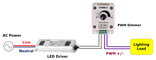
Pulse Width Modulation (PWM) Dimming
PWM or ‘Pulse Width Modulation’ works on a similar principle to that of mains dimming in that it is actually turning on and off the LED current for short periods of time and in the case of PWM dimming, the LEDs are driven with full amplitude pulses of current and the width of the pulses is varied to control the apparent brightness. The current is switched between the values of 0% and 100% of the rated output current which means that the LED source is either at zero current, when ‘OFF’ or at its full rated output current, when ‘ON’.
By definition, PWM power supplies have to run at frequencies high enough to be imperceptible to the human eye with this type of dimming being reliant upon the capability of the human eye to integrate the average amount of light in the pulses and providing that the pulse rate is high enough, the eye does not perceive the pulsing at all, only the overall average amount of light produced in the dimmed operation.
Where the frequency is less than 200Hz, users may observe visible flicker in their peripheral vision, and even higher frequency levels are required to eliminate stroboscopic effects in fast motion environments, resulting in a situation of, the higher the frequency, the less likely users will observe flicker. Higher-frequency power supplies are more complex, when very low light levels are desired, and the specification given may place minimum requirements on PWM frequency where the PWM dimming may be implemented either in the power supply or alternatively in the driver.

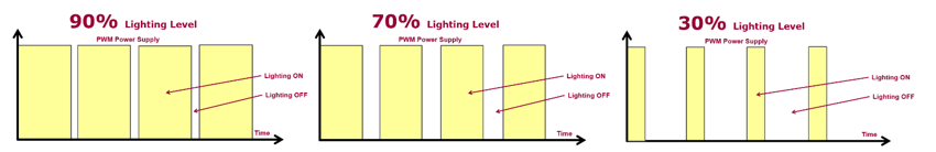
The current flows continuously at a set amount for a given light level. Since the amount of light output is proportional to the current flowing through the LED, the current is reduced to reduce the brightness of the LED. For example, as shown above, where the LEDs are driven with pulses of equal the ON-time and OFF-time, the system will achieve a level of 50% brightness (as shown above), however, the pulse rate must be high enough so that the eye perceives only the average light intensity. Further examples are shown below at 90%, 70% and 30% illumination levels.
With higher-frequency power supplies being complex as well as being more expensive to manufacture, especially when low light levels are desired and typically, a pulse rate of approximately 200Hz is considered high enough to achieve this objective, without any visible flickering. Due to the fast rising and falling edges of a Pulse Width Modulation driver, where faster edges allow for higher frequencies and assist in achieving lower dimming levels, an amount of electromagnetic interference (EMI) can be generated which may not be suitable for certain applications.
Pulse Frequency Modulation (PFM) Dimming
PFM or ‘Pulse Frequency Modulation’ dimming uses constant current pulses with constant pulse duration and the instantaneous junction temperature, due to self-heating is relatively constant. This means that the deviation from the self-heating free model is almost linear. During longer pulse durations, the more sustained self-heating will lead to slightly higher junction temperatures than shorter duty cycles.
PFM dimming is made up of a number of pulses of fixed duration, of whose frequency changes as the duty cycle decreases. The lag in heating is therefore constant throughout the whole dimming cycle, and so the temperature will decrease linearly. As this temperature decreases, so too, will the wavelength of the emitted light and the shift in chromaticity.
The advantages that PFM are a higher efficiency of emission, due to a reduced junction temperature, a raises in the possibility of feed-forward temperature compensation due to the linear nature of output flux and chromaticity shift in relation to duty cycle as well as the reduction in heat which will also result in improved lumen maintenance.
Pulse Code Modulation (PCM) Dimming
PCM or ‘Pulse Code Modulation’ (PCM) was invented in 1937 for telecommunication applications with the principle behind PCM being reasonably straightforward, where it is a device that converts a continuous physical quantity, usually voltage, into a digital number which represents the quantity’s amplitude. An analogue input signal is digitised with an Analogue/Digital Converter, which is defined by its band width and is the range of frequencies that it can measure and its signal to noise ratio in how accurately it can measure a signal relative to the noise it introduces.
The pulse code modulation technique is inherently completely digital and the duty factor of each PCM cycle is represented in a binary code, which means that a microcontroller needs to perform the operations of resolution. For a PCM channel with 12-bit resolution, this represents a reduction in computational load of over three orders of magnitude implemented in firmware. For PCM, the quasi-random sequence of pulses comprising each cycle tends to minimize the thermal cycling effects of PWM modulation when the drive frequency is less than 1000 Hz. There are of course some input values that will result in a single pulse per cycle, but they should occur only infrequently.
Each pulse has its own harmonic content. Phase shifting / delaying of these pulses does not alter their harmonic content, and so any set of PCM pulses can be phase shifted into an equivalent PWM pulse with the same duty factor and perhaps the greatest advantage of PCM is that it enables a single inexpensive microcontroller to independently control of the intensity of one hundred or more LED driver channels.
You Might Also Be Interested In...
