We are a leading manufacturer of quality internal and external lighting products for commercial, industrial and retail applications.
View all productsAt Ansell Lighting we design and manufacture an extensive range of luminaires for a diverse number of applications. Whatever the shape, purpose or style of your space, we have a lighting solution.
View all applicationsWe are a leading manufacturer of quality internal and external lighting products for commercial, industrial and retail applications.
About overviewOCTO delivers the complete smart lighting package to transform the efficiency and ambience of commercial and residential spaces.
OCTO overviewOur most commonly asked questions about lighting, LEDs and technical information.
All buildings in England are defined within one of the ‘Use Classes’ given in the Town and County Planning (Use Classes) Order 1987. The UK Government has implemented amended regulations, which came into force on the 1st of September 2020, to the Use Classes Order and the Permitted Development Rights.
From the 1st of September 2020, The Town and Country Planning (Use Classes) (Amendment) (England) Regulations 2020 came into force where parts of these regulations were either revoked or amended whilst they also created new use classes. Came into force 1st August 2021.
Read more in our blog.
The latest version of the Building Regulations 2010 for use in England was published on the 15th of December 2021, in two separate documents of the Approved Document L on the Conservation of Fuel and Power, with Volume 1 being for Dwellings and Volume 2 being for Buildings other than dwellings. take effect on 15th of June 2022.
Read more in our blog.
The standards of ANSI/IES LM-79-19, ANSI/IES LM-80-20 and ANSI/IES TM21-19 are documents which are all used to determine the performance metrics of LED light sources, listing the recommendations on the assessment of the maintenance of the luminous flux for LED-based lighting, and whilst they might work together, they do not in any way provide related measurements.
Read more in our blog.
The design and installation of anti-ligature lighting fittings are generally used within environments where individuals are considered to be deemed as being ‘at risk’, with the installation of a ‘Fixed hardware device’, being a light fitting, which performs a specific function when fixed or attached to a surface, having a fixing arrangement that is inaccessible or requires a special tool to release it from its mounting surface.
Read more in our blog article
All light sources degrade over time. LM80 is the method for measuring how much lumen depreciation the light source will suffer. This is not to be confused with an estimation of life. LED's typically do not fail as they have no filament to burn to end their life, rather degrade beyond useful life output.
The beam angle is the point at which the light output Lumens drop below 50% of the total light output. LED beam angles typically vary between 10° - 120°. The beam angle is the area where the light is at its most intense.
This is a luminaire that is free from points where a cord could be fastened to create a ligature point.
For further information, please refer to our Technical A-Z, which can be found at the back of our current catalogue & and also viewed as a PDF.
A light emiting diode is a device consisting of a semiconductor which emits light energy when an electrical current is passed through it. LEDs can be used for a variety of lighting applications.
Read more in our blog.
LED Strip is a well-known and often used lighting solution being based upon a number of LED surface mounted diodes, referred to as SMD chips, and is the most common light source used for LED Strip and are categorised using a four-digit number, which relates to their square or rectangular dimensions. SMD LED Strip is in either 12 Volt, 24 Volt or 48 Volt derivatives, with a number of LEDs contained within an individual circuit wired in series, and then the individual circuits are wired in parallel along the length of the LED Strip.
Read more in our blog.
The CIE provides a methodology for mapping the perceived colour onto the unit plane of an ‘x’, ‘y’ graph, where a pair of chromaticity coordinates for the light source corresponded to a unique colour point of light, with its use being a measure of colour difference of a light source and which has become common practice in the lighting industry.
Read more in our blog.
The method for Colour Quality Scale is derived from the sample test method used in the CIE Colour Rendering Index but is based upon a pallet of 15 Munsall sample colours which were selected to overcome the limitations of CRI, where it disadvantages light sources which show increased object saturation when viewed against the reference illuminant.
Red more in our blog.
Light sources all have a colour temperature which will dictate whether the light emitted is either of a warm colour, an intermediate or neutral colour, a cool colour or a cold colour. The higher the colour temperature, the cooler, the colour appearance of the light source. The Colour Temperature is a description of the warmth or coolness of a light source. It is most simply, a method of demonstrating the colour characteristics of light, usually either as warm (yellowish) colour or a cool (bluish) colour.
Read more in our blog.
There are four types of dimming shown here:
Corridor Function is a setting of DD dimmable control gear for operation with a PIR (standard on/off). Dimmable control gears reduces light output to 3-5% when an area is unoccupied and increases to full light output when PIR is activated.
Yes, with equipment that facilitates this, normally a dimmable LED driver, along with a suitable dimmer switch. All of our LED products are highlighted in our catalogue as either “dimmable” or “non-dimmable”.
DALI – Digital Addressable Serial Interface = DD3
DALI is a two-way communication system that brings digital technology to lighting and is an international standard for communication, where DALI defines the commands that ballasts need to recognise in order to be considered DALI ballasts.
The system allows individual ballasts to “talk” to the user and allows the user to “talk” back via DALI controllers, computers equipped with appropriate software, or building management systems (BMS). DALI sends messages around, and just like computer networks, those messages are picked up by the ballasts via addresses and the ballast with that address picks it up and follows the instruction given.
Read more in our blog.
DSI – Digital Serial Interface = DD2
The DSI system was launched into the lighting market back in 1992 and is a more controllable version of digital dimming, which enables the user to group luminaires, operate daylight linked dimming as well as other control options.
The term DSI is a Tridonic name which can be set up with a variety of controls and controllers, some of which are offered by other manufacturers but designed to work with the DSI control gear. When launched, was the first use of digital communication in lighting control and is the precursor to DALI.
Read more in our blog.
Dimming residential lighting allows the homeowner to achieve the desired levels of illumination within a room and consequently alter the mood of the environment. The most popular system for a residential lighting installation is known as ‘Phase-cutting’ dimming.
Phase Dimmers works by ‘chopping’ out a part of the mains voltage to the light source which reduces the power being supplied, resulting in a variation of the brightness of the lamp. Delaying the start or prematurely ending of the phase half-cycle of AC power is known as “phase control” which will regulate the amount of power to the lamp.
There are two types of phase dimming:
Leading Edge Dimming, often referred to as “Triac” or Incandescent Dimming Trailing Edge Dimming often referred to as ELV Transformer Dimming
Switch-Dim = DD1
The concept of a Switch-Dim system is a simplified dimming method which uses a 230 Volt Mains frequency as a signal transmitter through a simple retractive (non-latching) switch.
The Switch-Dim operation is a cost-effective dimming and switching control system using an impulse as the regulator, which is basically a switch with a built-in reversing spring, and as such, the system will work with many of the commercially available push-to-make switches.
Read more in our blog.
There are a number of types of dimming commonly used for LED lighting:
Pulse Width Modulation Dimming (PWM) works on a similar principle to that of mains dimming in that it is actually turning on and off the LED current for short periods of time and in the case of PWM dimming, the LEDs are driven with full amplitude pulses of current and the width of the pulses is varied to control the apparent brightness.
The current is switched between the values of 0% and 100% of the rated output current which means that the LED source is either at zero current, when ‘OFF’ or at its full rated output current, when ‘ON’.
There are two types of Analogue Dimming, where both are collectively referred to as being Analogue Dimming
0-10 Volt Analogue Dimming
1-10 Volt Analogue Dimming
Both use separate AC power and control supply with one-way communication where the mains power to each of the luminaires in the circuit requires the installation of a 3 core mains supply (Live/Earth/Neutral). The control function is by an additional signal pair cable which carries a low-speed signal, only used to control the dimming level and the usual method of control for this type of dimming system is typically by means of either a rotary dimmer or slider potentiometer.
Read more in our blog.
The terms of ‘Luminance’ and ‘Illuminance’ appear at first glance to have the same or at the very least a similar meaning, however nothing could be further from the truth. Luminance relates to the amount of light emitted, which either passes through, or is reflected from a surface, whereas Illuminance relates to the amount of light which actually lands on a surface.
Read more in our blog.
European Union – Commission Regulation (EU) 2019/2020
United Kingdom – Statutory Instrument 2021/1095
The above legislation very much aligned and provides information on a “containing product”, being detailed as a product containing one or more light sources, or separate control gears, or both, including, but not limited to, luminaires that can be taken apart to allow separate verification of the contained light source(s).
Information shall be provided by the manufacturer regarding the replaceability or non-replaceability of light sources and control gears by either professional persons or end-users without permanent damage to the containing product.
Read more in our blog.
Track mounted lighting equipment is immensely popular and has been used to offer flexibility in highlighting featured objects within many types of environments.
There is two options, Mains Voltage (230Volt) track system which has a mains supply directly into the Live End of the track or a Low Voltage track system which has a reduced voltage supply to the track, such as 24 Volts, with the electrical supply from the mains being operated through a 24 Volt Constant Voltage Non-Dimmable LED Driver positioned remotely.
The greatest benefit from track lighting is that it offers adaptability and flexibility of the system to meet the specific needs of the customer at any time without having to call an electrical contractor to undertake this for you.
Read more in our blog.
Thermoplastic materials used as diffusers in light fittings provides a significant hazard in a fire, where burning droplets can rapidly increase the fire growth rate and smoke produced, which produces extremely hazardous conditions.
When these light fittings are installed to form an integral part of a ceiling (i.e. recessed) they must be either categorised as being TP(a) or TP(b) rated and are to be installed in accordance with the Building Regulations of the appropriate devolved country, in respect of Fire Safety and for the relevant TP rating.
Read more in our blog.
Panels that form part of a ceiling (i.e. recessed) must be either TP(a) or TP(b) rated and be installed in accordance with the Part B regulations relating to that rating.’
TP(a) rating
Thermoplastic materials undergo specific tests to certify their ability to withstand the application of heat and fire. The requirements are established by Building Regulations Approved Document B, which sets out the fire safety of buildings. Section B2 covers internal fire spread.
TP(a) usually relates to polycarbonate diffusers with a thickness of at least 3mm. The testing procedure requires that the material self-extinguishes and any flaming and afterglow must not exceed five seconds, once the source of flame is removed.
There is no restriction on the use of TP(a)-rated diffuser material.
TP(b) rating
TP(b) materials tend to be acrylic or polystyrene. It is a more problematic material because its use is limited by the extent of the installation. The testing for TP(b) requires a flame to be presented to the material. If the material combusts, the spread of flame must be no more than 50mm per minute – that’s 12 minutes to completely blanket a 600mm wide panel.
In circulation spaces, the total area of diffuser panels must not exceed 15 per cent of the total floor area. The maximum area of one diffuser, or group of diffusers, must not exceed 5m x 5m. There must be a 3m spacing between each 5m x 5m diffuser grouping.
Read more in our blog.
The diffuser material is to be subjected to a naked flame for 10 seconds and the time taken for the sample to burn between two marks positioned 25mm and 125mm from the end of the sample is measured.
The results of the test will provide the classification of TP rating, where for TP(a), the flame self-extinguished and any afterglow extinguished within 5 seconds of the flame extinguishing and for TP(b), the flame continued to spread along the material but burned at a rate of less than 50 mm/minute.
Read more in our blog.
LED drivers are supplied either Constant Current or Constant Voltage. Both require the LED chips / modules to be wired differently (CC- Series; CV- Parallel).
There are three classified zones and a further zone which is for installations classed as being outside of the other zones
Zone 0 is the area inside the bath or in the shower tray itself and if lighting is required, any fitting which is used must be LV, to a maximum of 12Volts and rated to at least IPX7.
Zone 1 is the area above the bath or shower tray up to a height of 2250mm from the bathroom floor with any fitting installed having a minimum IPX4 rating and if there is a likelihood of water jets being used for cleaning purposes, replace lighting to IPX5.
Zone 2 is the area extending to 600mm outside the perimeter of the bath and to a height of 2250mm from the bathroom floor with any fitting having a minimum IPX4 rating. It is good practice that the area around a wash basin, within a radius of 600mm of any tap is Zone 2 and if there is a likelihood of water jets being used for cleaning purposes, replace lighting to IPX5.
The areas deemed to be outside the Zones are anywhere within the bathroom which are located outside of Zone 0, Zone 1 & Zone 2, subject to their specific limits and where no water jet is likely to be used. Any fitting installed need not have any ingress protection, however if there is any likelihood of water jets ever being used replace the lighting to IPX5.
Full details can be found in the IEE Wiring Regulations.
Read more in our blog article.
All electrical devices are tested to determine a level of resistance against the intrusion of solids and liquids.
Once tested, the product is given an IP rating, which stands for Ingress Protection. IP Rating uses a two-digit code where the first digit is a number value of between 0 & 6, for protection against ingress from a solid object, and the second digit is a number value of between 0 & 9, for resistance against ingress of moisture.
Ingress protection is important as it allows the safe use of lighting equipment within environments where it is possible dust particles and water may get into the fitting and having a suitable IP Rating will give customer confidence in purchasing lighting fittings which are suited to the application into which they are to be installed.
Read more in our blog article
The classification of the degree of protection provided by enclosures, including those containing electrical lighting equipment against mechanical impact.
The term ‘IK’, where the ‘K’ part stands for ‘Kinetic’ relates to the motion of material bodies and the forces of energy associated with them.
IK ratings are defined as IKXX, where “XX” is the number from 00 up to 10, indicating the degree level of protection provided by the enclosure, which includes those containing luminaires, against external mechanical impacts.
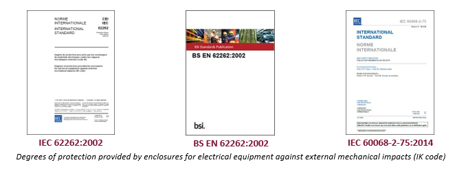
IEC 62262:2002 and BS EN 62262:2002 describe a system for classifying the degrees of protection provided by enclosures for electrical equipment against external mechanical impact (IK Code). Whilst this system is suitable for use with most types of electrical equipment, it should not be assumed that all the listed degrees of protection are applicable to a particular type of equipment.
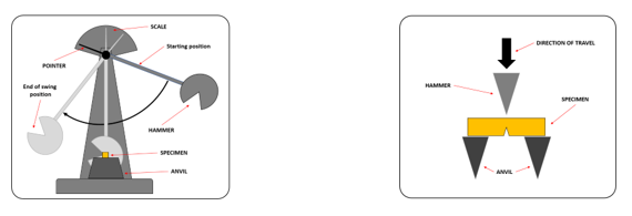
IEC 60068-2-75:2014 provides further detail where this part of IEC 60068 provides three standardized and coordinated test methods for determining the ability of a specimen to withstand specified severities of impact. It is used, in particular, to demonstrate an acceptable level of robustness when assessing the safety of a product and is primarily intended for the testing of electrotechnical items. It consists of the application to the specimen of a prescribed number of impacts defined by their impact energy and applied in the prescribed directions. This part covers energy levels ranging from 0,14j (joules) to 50j (joules).
The degree of protection applies to the complete enclosure and testing is carried out within a temperature range of 15°C - 35°C at an atmospheric pressure of between 860mb and 1060mb and is based upon testing of a new enclosure and to verify protection against mechanical impact, blows shall be applied to the enclosure being tested which is based upon 5 impacts to each face of the enclosure.
IK ratings are defined as IKXX, where “XX” is the number from 00 up to 10, indicating the degree level of protection provided by the enclosure, which includes those containing luminaires, against external mechanical impacts. This is of importance when considering the installation of lighting equipment for the more arduous applications, such as in sports centres and also outdoor working areas, such as in construction.
The different levels of IK ratings relate to the ability of the enclosure to resist varying impact energy levels measured in joules (j) and the International Electrotechnical Commission document, IEC 62262:2002 denotes how protected an enclosure (light fitting) is from mechanical impact, with the ratings at the higher end providing greater tolerance for impact. The British Standard version is BS EN 62262:2002 and is the UK version of the EN Standard, which in turn is the European version of the international standard.
UK - SI 2013 No. 3113 – The Waste Electrical and Electronic Equipment Regulations 2013
EU - DIRECTIVE 2012/19/EU
The WEEE Regulations/Directive is environmental legislation. It aims to address the environmental impacts of WEEE, and to encourage its separate collection, and subsequent treatment, re-use, recovery, recycling and environmentally sound disposal.
Waste electrical equipment is identified by the crossed-out wheelie bin symbol on the product or its packaging. This symbol means that the product should be disposed of sustainably and not as part of unsorted municipal waste.
When waste electrical equipment is sent to landfill this results in hazardous chemicals being released into the environment which has a negative impact on wildlife and human health. Alternatively, this equipment should be taken to your local recycling centre.
Ansell Electrical Products Limited (Warrington) – Registration Number: WEE/FH0429XT
Ansell (Sales & Distribution) Limited (Belfast) – Registration Number: WEE/MM4520AA
When supplied as B2B EEE the producer invokes regulation 12.2 and passes all WEEE obligations to the B2B end user.
Ansell (Sales & Distribution) Republic of Ireland Ltd – Registration Number: 3209WB
Waste Electrical and Electronic Equipment (WEEE) is taken back free of charge on a one-for-one, like-for-like basis. Waste batteries including rechargeable batteries are taken back free of charge. You are not obliged to make any purchase when returning old batteries. Each local authority must also accept household WEEE and small batteries free of charge at its recycling facilities. All WEEE and waste batteries must be recycled and should not be placed in any of your household wheelie bins. Make sure you always recycle all your old electrical goods and batteries.
Recycle IT are the approved recycling agent of WEEE Ireland:
RECYCLE IT, Clondalkin Community Recycling Initiative Limited, Unit 14/2 Crag Terrace, Clondalkin Industrial Estate, Clondalkin, Dublin 22
Ansell Electrical Products Spain, S.L. – Registration Number: 7249 & 2020
The latest version of the Building Regulations 2010, Volume 2 being for Buildings other than dwellings for use in England offer details of the calculation process is given as a series of steps, for determining the value of LENI and shall be given in terms of kilowatt hours per square metre of the area per year (kW/m2/year).
Read more in our blog article
European Union – Commission Regulation (EU) 2019/2015
United Kingdom – Statutory Instrument 2021/1095
Each light source placed on the market as an independent product, not in a containing product, and in packaging, is supplied with a label, printed on that packaging is required to rescale products using a printed label, provided as a sticker, of the same size as the one which already exists at the point of sale within eighteen months after the application of the Regulation.
Read more in our blog.
Firstly, the installation of any lighting control within an application can provide significant benefits, not only in energy saving, but also in the continued specified performance and the economic life of the lighting fittings.
There are three basic types of control to consider.
Photo Electric Cell Units are basically a switch which operates automatically based upon the amount of ambient light and their function is in two different operations, to switch the lighting on when the ambient lighting level falls below a given value and to switch the lighting off when the ambient lighting level rises above the given value.
Microwave sensors operate by emitting a high frequency microwave beam over a designated area and when that beam is invaded by motion, this determines presence and activates the lighting to be switched on. An ideal solution for external lighting applications as they do not require a hole to be cut into the luminaire.
Passive Infra-Red Sensors (PIR) are electronic sensors which measure Infra-red light radiating from objects within the field of view, working where infra-red radiation enters the segmented front.
Read more in our blog article.
Ansell Lighting offer a “Return to Base” warranty on their products. Our sole obligation under this warranty is to repair or replace any defective product(s) during the warranty period. Any products replaced or repaired by Ansell under warranty, will be warranted for the balance of the original warranty period.
LED warranty period is based on an average usage of eight hours per day and applies where failures exceed a component manufacturers expected failure rate and lumen depreciation.
It is essential that battery packs within all emergency luminaires are replaced after a four-year period. All emergency luminaires must be tested in accordance with BS EN 5266-8-2004. Increased frequency of emergency testing may result in the premature replacement of battery pack, before the standard four-year period. Batteries are supplied with a 2 years warranty only.
The definition of glare is the visual sensation caused by an excessive and uncontrolled brightness of light within the individual’s field of view.
There are two forms of glare, Disability Glare which is defined as directly impairing vision and Discomfort Glare which is defined as perceived discomfort.
There are two types of Glare. Direct Glare which is caused because of high levels of brightness from a light source. Indirect Glare, which is caused by reflected brightness, where the direct light from the source is reflected off a bright surface.
Read more in our blog.
Glare is a common problem within interior workplaces, which can be caused by inappropriate luminaires giving excessive brightness either directly into the line of sight of individuals or can be because of being ‘bounced off’ reflective surfaces, such as computer screens, whiteboards, etc.
This can cause significant disruption for the occupants of interior workspaces such as in offices, in terms of individuals experiencing headaches & eye trouble, leading to employee absences.
Read more in our blog article.
Generally, the completed project will have been sent out as a single document, created from a portfolio of sections contained within the printout section of the lighting software programme and in reviewing the technical aspects of each design, the best advice on offer for individuals reviewing a received lighting scheme, is to make a proper comparison between each of the designed solutions based wholly upon the technical attributes of the design, rather than that of just the bottom-line quotation value.
Read the blog article to learn more.
The standard states that the emergency lighting scheme design should be based upon worst conditions with minimum light output and maximum glare limits of luminaires during operating life and based only on direct light from luminaires.
The standard states in relating to emergency escape lighting system design, in which the provision of a highly reliable emergency escape lighting is essential and the illumination provided by the emergency escape lighting system of a compartment of the escape route shall be from two or more luminaires, so that the failure of one luminaire does not plunge the route into total darkness or make the directional finding effect of the system ineffective.
Please read our blog for more information.
he requirements for emergency lighting are given in a number of standards, namely BS 5266-1:2016, BE EN 1838:2013 and BS EN 50172:2004 and where the Ansell Wolf provides the ideal solution in being a modern, robust die-cast aluminium low glare wall pack fitting, suitable for both commercial and industrial applications.
Read more in our blog article.
These fittings utilise an accurate internal clock which is programmed to interrupt the permanent mains supply at set intervals, thus initiating emergency lighting tests. These units are supplied pre-programmed to initiate short duration tests once every month, a one third duration test after six months and a full duration test once every 12 months.
Read our blog here.
A Self-Test system is basically an intelligent emergency system, which is integral to each luminaire, and which conducts routine functional and duration testing in-line with the relevant standards, providing great benefits to the end user client in that previously conventional techniques used for the testing procedure were reliant upon the manual process, where the automated system offers full compliance, without the need for the outdated manual process.
Read more in our blog.
Firstly, the procedure for the testing of the emergency lighting equipment installed within buildings is a mandatory requirement to allow the occupants the opportunity to escape safety in the event of an emergency.
The following minimum inspections and tests shall be carried out at the intervals recommended to and the regulating authority may require specific tests.
Daily – Indicators shall be visually inspected for correct operation.
Monthly – Short duration tests by switching on, in the emergency mode, each luminaire and each internally illuminated exit sign from its battery
Annually – Full rated duration test in accordance with the manufacturer's information.
The Wi-Fi system was launched for consumer use back in 1997 and in the same year, the Institute of Electrical and Electronics Engineers created the first WLAN (Wireless Local Area Network) standard, which is a method of wireless distribution taking place between two or more devices, using high-frequency radio waves, which includes an access point to the Internet, allowing its flexible and continued use whilst remaining within the area of coverage.
Read more in our blog.
The pupil lumens is a measurement of the light which stimulates the rods within the eyes to determine the scotopic lumen output and the total visually effective number of lumens to illuminate an installation.
Read more in our blog.
The basic answer is the ‘Watt’ is a measurement of energy consumption, whereas the lumen is a measurement of light output, and the idea of installing more power to gain more light is now not considered as being either energy efficient or environmentally sustainable.
Read more in our blog.
The term ‘battery’ is used to describe a chemical device two or more cells which has the ability to store chemical energy and is converted into Direct Current. Whilst everyone calls this a ‘battery’, its correct term is in fact a ‘cell’.
There are basically two different types of batteries, a Primary Battery, which is not rechargeable and a Secondary Battery, which is rechargeable.
The types of rechargeable cells used for emergency lighting are:
NICKEL CADMIUM = Ni-Cd (Ni-Cad)
NICKEL METAL HYDRIDE = Ni-MH
LITHIUM ION – Li-Ion
LITHIUM IRON PHOSPHATE – LiFePO4
Read more in our blog.
It is the intention of gaming enthusiasts to create the ideal environment in which they can achieve most from the gaming experience and it would appear that performance can be directly attributed to having an ideal lighting installation within the space.
Creating that optimum environment needs a different approach and the solution is by electric lighting, where the ambience can be created by the use of appropriate lighting equipment which can be used during the periods of gaming.
Warm lighting colours within the space can induce an atmosphere of relaxation, a situation to be avoided, whereas the cooler colours of a higher colour temperature towards that of daylight, alongside the introduction of higher levels of illuminance are considered as being more beneficial in creating an environment where the gamer can concentrate and remain alert over longer periods of duration, whilst also enhancing the aesthetic appeal of the space.
Read more in our blog article.
Emergency lighting is provided for use when the power supply to the normal lighting fails and therefore must be powered from a source independent of that supplying the normal mains lighting.
It is a mandatory requirement to allow the occupants the opportunity to escape safety in the event of an emergency
There are a number of documents published for emergency lighting:
BS 5266-1:2016 – Emergency lighting - Part 1: Code of practice for the emergency lighting of premises
BS EN 1838:2013 – Lighting Application – Emergency Lighting
BS EN 50172:2004 (BS 5266-8:2004) – Emergency escape lighting systems
According to BS EN 50172:2004, the purpose in the provision of emergency escape lighting is to ensure that lighting is provided both promptly and automatically and for a suitable duration of time, upon the failure of the power supply to the normal lighting.
With regard to routine inspections and tests, BS 5266-1:2016 states that the emergency lighting systems should be inspected and tested at regular intervals in accordance with BS EN 50172 and where a functional operation should be checked at least every month. The testing of full rated duration should be performed on each emergency luminaire at least annually.
Read more in our blog.
There is, the Adler Exit Sign, from Ansell Lighting is that one for all solution, in offering five different mounting options of suspended, recessed, surface, wall surface and side arm wall mounting, as well as 2-part legends allowing the option of multiple directions from just one legend kit.
Read the blog article to find out more.
he installation of emergency lighting and signage needs to be provided within many types of buildings, as this allows for employees and visitors to safely evacuate the building to a place of safety in the case of an emergency.
The signage should be installed so that there is no ambiguity as to the direction required to safely escape from the building.
Read more in our blog.
The first point to get across is that lighting installed within the vicinity of a bat roost, which is deemed to cause disturbance to the bat or it’s roost, may constitute a legal offence.
Before installing any lighting equipment, and if it is known that a bat population is located, then the appropriate bat safety group should be consulted in order that they can assess the situation.
In considering the location of lighting fittings, the bat roost, as well as including the access points, should NOT be directly illuminated under any circumstances.
The design of lighting installation needs to be implemented with extreme care and this is best achieved by contacting a lighting designer at Ansell Lighting to assist in this process.
Read more in our blog article.
The 3 Highbay and single Lowbay variances, encompass 15 different wattage and lamp colour options of luminaire selection across the range, and with the various additional dimming, lighting control, emergency, and sensor options, as well as a range of reflector, lens, and mounting bracket assemblies, this makes this an extensive range, which presents the specifier with the opportunity to select the optimum fitting solution for their particular application.
Read more in our blog.
To assist customers in lighting projects where a single floodlight is to be installed onto a single column, Ansell Lighting has added to the Aztec range of floodlights, single post-top brackets and column clamps for the most common tubular steel columns used in many commercial and industrial applications, that being for 76mm and 60mm diameter tubular steel lighting columns.
Read more in our blog.
An LED normally consist of a single p-n junction diode, which is the basic building block of solid-state electronics and is the simplest possible semi-conductor device, where by connecting the P-type material to the positive terminal of a power source and the N-type material to the negative terminal of the same power source, as shown in the image below, an electric field can then be created across the diode, thereby creating visible light.
Read more in our blog.
There are those who believe that operating LED lamps and LED luminaires within lighting applications provides the user with a cool to touch scenario, however this is not the case and it is generally accepted that LED light sources are around 45% efficient, which means that the remaining 55% of energy is in the form of heat, which is transferred between the elements in two different ways, that of thermal conduction and thermal convection.
Read more in our blog.
Get monthly news, tips, and new product updates delivered straight to your inbox.
Email addresses are never sold or given out to anybody. By subscribing, you agree to our Privacy Policy and Terms.